PH
PHjcdgreatest
Fanatic
Dear All,
I hope everyone is doing well.
It has been a while since I last posted any updates. After several months of development and testing, I finally have a working prototype of my DIY Piso WiFi system built completely from scratch.
Since I have been away from the community for several years, I'm a little concerned that my design may already be outdated compared to the latest commercial systems. Nevertheless, I wanted to share my work because it may still be useful to those who enjoy building their own hardware and software instead of purchasing ready-made solutions.
Unlike most commercial Piso WiFi systems, this prototype does not rely on subscription services or cloud-based software. Everything is hard-coded and runs locally, which means you are free to customize the code to suit your own requirements.
✔ Automatic voucher generation
✔ Wireless communication between ESP-12E and MikroTik
✔ Automatic voucher activation
✔ Coin acceptance lockout to prevent accidental coin insertions
✔ Relay-controlled coin slot and indicator LEDs
✔ Fully offline operation (no cloud services or subscriptions required)
✔ Compatible with Mikhmon voucher generation
For those who are interested in this journey, feel free to ask questions. I'll gladly share what I've learned during the development process.
Price: Approximately ₱1,745
Price: Approximately ₱175
Although the MikroTik hAP Lite already includes built-in WiFi, I intentionally chose to use a dedicated outdoor AP because I believe each device should perform the task it does best. By allowing the MikroTik to focus on routing and hotspot management while the COMFAST handles wireless connectivity, the system becomes more efficient, scalable, and easier to maintain. The outdoor design also provides better coverage and weather resistance, making it ideal for Piso WiFi installations.
Price: Approximately ₱1,900–₱2,500
Price: Approximately ₱40–₱80
Price: Approximately ₱500–₱900
Price: Approximately ₱250–₱400
Price: Approximately ₱44–₱150
This is only the first prototype. I already have several ideas planned for future versions, including additional features, improved reliability, and a better user experience.
I hope this project can inspire fellow hobbyists, students, and DIY enthusiasts who want to build their own Piso WiFi system from the ground up instead of relying solely on commercial packages.
My objective was not simply to assemble existing modules, but to understand how each component works and to develop a modular Piso WiFi platform that I can continuously customize and improve. Every line of code running on the ESP-12E and every customization made to the MikroTik hotspot was written, tested, and refined specifically for this project.
I hope this journey encourages others to learn, experiment, innovate, and build rather than simply copy.
Thank you, and I look forward to hearing your suggestions, feedback, and ideas.
If you find this project helpful and would like to support its continued development, you may send a donation via GCash: 0933-859-6109. A simple Like, Follow, or Share would also be greatly appreciated.
End of Day 1 – The Journey Begins.
IP Address:
You may choose a different IP address if desired, but if you do, remember to update the corresponding settings in the ESP firmware and any scripts that communicate with the MikroTik.
This approach provides several long-term benefits:
Designing for future expansion from the beginning saves time and avoids unnecessary reconfiguration as your Piso WiFi network grows.
The EW72 is a dual-band outdoor access point, meaning it supports both:
This allows older devices to connect on 2.4 GHz, while newer phones can take advantage of 5 GHz for faster browsing, streaming, and downloads.
ISP → MikroTik (10.0.0.1) → COMFAST EW72 → Client Device
In this design:
The AP should operate in Bridge (Access Point) mode so that:
I suggest a unique SSID which is more appealing and eye catching, mine i am using K
K FAST
FAST NET
NET 2G & KFASTNET5G - you could use other several UTP-8 characters of your liking.
Attached is You do not have permission to view the full content of this post. Log in or register now. folder that you could migrate to mikrotik.
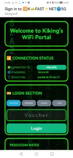
We shall walk through with Login.html.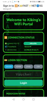
One of the strongest aspects of our login.html is that it is designed with fail-safe behavior rather than assuming everything will always work correctly. Each stage has a fallback path so the customer can still use the hotspot even if part of the system fails.
Our login page acts as the coordinator between three independent systems:
Instead of relying on a single component, each system can continue operating even if another temporarily becomes unavailable.
This protects against situations such as:
If the coin slot is already active, additional users are placed into a waiting state rather than being allowed to interfere with the current transaction.
This prevents:
This eliminates several common user errors, including:
If the controller cannot be reached, the login page does not freeze or crash. Instead, it gracefully returns the customer to the normal login interface, allowing voucher login to continue manually.
This means the hotspot remains usable even if the ESP controller is temporarily offline.
If no coin is detected within the allowed time, it automatically:
Although browsers cannot guarantee that this notification will always be delivered, it provides an additional layer of cleanup that complements the ESP controller's own timeout mechanisms.
In practical terms, our architecture is designed to ensure that:
This layered approach is closer to the reliability principles used in industrial automation than to the simpler captive portals commonly found in commercial Piso WiFi systems, where the browser often acts only as a login form. Here, the browser actively participates in coordinating transactions while still allowing recovery from common failure scenarios.
Below are the screenshots of alogin.html, Status.html, and Logout.html, BTW my theme was inspired by "The Matrix" Movie
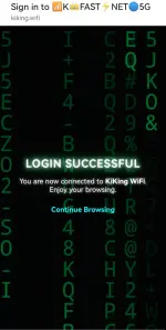
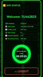
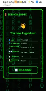 i,i
i,i
End of Day 2 - Tomorrows preview Arduino IDE, ESP-12E coding. Please continue with this journey with me.
2. After configuring download this file You do not have permission to view the full content of this post. Log in or register now.
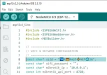
3. Please take note on this configurations. you need to change on your configuration.
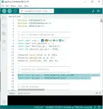
4. Above screenshot on line 13. that will set your ESP-12E/8266 IP to 10.0.0.150, you could change this on your preferred IP add. this is also declared on login.html line 282 below

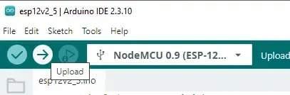
5. Save your updated ino file, then upload your program to your esp-12e/8266
6. Now connect your NodeMCU ESP-12E Development Board (ESP8266)
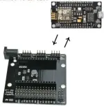
7. The coin slot has 3 or 4 wires,
- Red wire connect to relay common
- Black wire connect to labeled GND pins, below outer pins
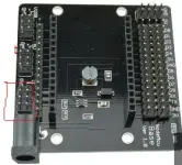
- Labeled "coin wire" connect to D3,
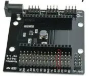
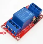
8. 12V Relay "IN" connect to board pin labeled D1
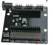
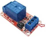
- 12V Supply DC+ and DC- connect to below, outer pins are GND, while inner pins are +12V
- Relay NO (normally open) connect to board inner pin
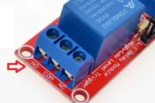
9. you can now connect your 12v power supply preferably 1.5amps on your board.
10. ESP-12E will now CONNECT to your wifi SSID
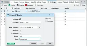
11. Your ESP-12E IP must be registered to your MIKROTIK>HOTSPOT>FIREWALL>IP_Bindings and set TYPE to bypassed
12. Now go back to your Arduino IDE app. On menu "Tools", click Serial Monitor.
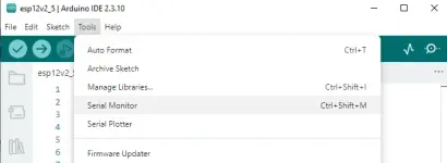
- this will open a window beneath the coding area- select 115200 baud rate
View attachment 4263651
- reset your ESP-12E, and check the information/feedback on the serial monitor. the below message is confirming that it had successfully connect to your wifi
View attachment 4263653
End of Day 3 - Tomorrows preview Testing and Troubleshooting

I hope everyone is doing well.
It has been a while since I last posted any updates. After several months of development and testing, I finally have a working prototype of my DIY Piso WiFi system built completely from scratch.
Since I have been away from the community for several years, I'm a little concerned that my design may already be outdated compared to the latest commercial systems. Nevertheless, I wanted to share my work because it may still be useful to those who enjoy building their own hardware and software instead of purchasing ready-made solutions.
Unlike most commercial Piso WiFi systems, this prototype does not rely on subscription services or cloud-based software. Everything is hard-coded and runs locally, which means you are free to customize the code to suit your own requirements.
Design Philosophy
Rather than expecting one device to do everything, I designed the system so that each component performs the task it does best.- MikroTik – Router, hotspot, voucher management, bandwidth control, and user authentication.
- ESP-12E – Coin validation, vending logic, and wireless communication with the MikroTik via the RouterOS API.
- COMFAST CF-EW72 – Dedicated dual-band outdoor access point that provides reliable wireless coverage for client devices.
Current Features
✔ Coin slot validation✔ Automatic voucher generation
✔ Wireless communication between ESP-12E and MikroTik
✔ Automatic voucher activation
✔ Coin acceptance lockout to prevent accidental coin insertions
✔ Relay-controlled coin slot and indicator LEDs
✔ Fully offline operation (no cloud services or subscriptions required)
✔ Compatible with Mikhmon voucher generation
For those who are interested in this journey, feel free to ask questions. I'll gladly share what I've learned during the development process.
Major Components and Estimated Cost
1. MikroTik hAP Lite
Serves as the brain of the WiFi system. It manages the hotspot, voucher generation, user authentication, and Piso rate configuration.Price: Approximately ₱1,745
2. NodeMCU ESP-12E Development Board (ESP8266)
Acts as the controller for the coin slot. It validates inserted coins, communicates wirelessly with the MikroTik through the RouterOS API, and manages the vending logic.Price: Approximately ₱175
3. COMFAST CF-EW72 Dual-Band Outdoor Access Point
Serves as the wireless Access Point (AP) that broadcasts the WiFi signal to clients.Although the MikroTik hAP Lite already includes built-in WiFi, I intentionally chose to use a dedicated outdoor AP because I believe each device should perform the task it does best. By allowing the MikroTik to focus on routing and hotspot management while the COMFAST handles wireless connectivity, the system becomes more efficient, scalable, and easier to maintain. The outdoor design also provides better coverage and weather resistance, making it ideal for Piso WiFi installations.
Price: Approximately ₱1,900–₱2,500
4. 12V Relay Module
Provides power to the coin acceptor only when the system is ready to receive coins, preventing accidental insertions. It also controls the indicator LED lamps, helping reduce unnecessary power consumption when the system is idle.Price: Approximately ₱40–₱80
5. Electronic Coin Acceptor
Accepts and validates coins before sending pulses to the ESP-12E.Price: Approximately ₱500–₱900
6. 12V DC Power Supply
Supplies power to the relay, coin acceptor, and other peripherals.Price: Approximately ₱250–₱400
7. LED Indicator Lamps
Indicate when the coin slot is active and ready to accept coins, providing a clear visual cue for users.Price: Approximately ₱44–₱150
This is only the first prototype. I already have several ideas planned for future versions, including additional features, improved reliability, and a better user experience.
I hope this project can inspire fellow hobbyists, students, and DIY enthusiasts who want to build their own Piso WiFi system from the ground up instead of relying solely on commercial packages.
My objective was not simply to assemble existing modules, but to understand how each component works and to develop a modular Piso WiFi platform that I can continuously customize and improve. Every line of code running on the ESP-12E and every customization made to the MikroTik hotspot was written, tested, and refined specifically for this project.
I hope this journey encourages others to learn, experiment, innovate, and build rather than simply copy.
Thank you, and I look forward to hearing your suggestions, feedback, and ideas.
If you find this project helpful and would like to support its continued development, you may send a donation via GCash: 0933-859-6109. A simple Like, Follow, or Share would also be greatly appreciated.
End of Day 1 – The Journey Begins.
Day 2 – July 22, 2026
MikroTik Configuration
Before proceeding, make sure your MikroTik router has been reset to its default configuration or is in a known working state.Step 1 – Configure Your MikroTik
There are many excellent MikroTik setup tutorials available online. Since this guide focuses on the Piso WiFi system, I won't cover every RouterOS setting in detail. If you're new to MikroTik, I recommend following a basic hotspot configuration tutorial first.Step 2 – Set the MikroTik IP Address
For this project, I configured the MikroTik with the following management IP address:IP Address:
10.0.0.1You may choose a different IP address if desired, but if you do, remember to update the corresponding settings in the ESP firmware and any scripts that communicate with the MikroTik.
Step 3 – Configure the Ethernet Ports
One advantage of building your own system is the flexibility to design it for future expansion.My Recommended Port Configuration
| Port | Function |
|---|---|
| Ether1 | ISP / Internet (WAN) |
| Ether2 | Access Point (AP) |
| Ether3 | Access Point (AP) |
| Ether4 | Access Point (AP) |
Why configure all remaining ports as AP?
Many online tutorials recommend the following setup:- Ether1 – ISP (WAN)
- Ether2 – LAN
- Ether3 – LAN
- Ether4 – AP
This approach provides several long-term benefits:
- Easier network expansion without reconfiguring the router.
- Supports adding multiple wired Access Points as your business grows.
- Allows better Wi-Fi coverage for larger areas.
- Simplifies future upgrades, such as sector antennas or additional outdoor APs.
- Keeps the network design consistent and scalable.
Designing for future expansion from the beginning saves time and avoids unnecessary reconfiguration as your Piso WiFi network grows.
Access Point (AP) Configuration
Step 1 – Access Point Model
For this build, I am using the COMFAST EW72.The EW72 is a dual-band outdoor access point, meaning it supports both:
- 2.4 GHz
- 5 GHz
Why I Chose a Dual-Band Access Point
2.4 GHz – Better Range
Use this band when:- The client is farther away from the AP.
- There are walls or other obstacles between the client and the access point.
- Maximum coverage is the priority.
- Longer range
- Better wall penetration
- Compatible with almost all phones and devices
- More interference from neighboring Wi-Fi networks
- Lower maximum throughput compared to 5 GHz
5 GHz – Better Speed
Use this band when:- The client is relatively close to the AP.
- There is a clear line of sight.
- Higher speed and lower latency are desired.
- Higher throughput
- Lower interference
- Better performance when many clients are connected
- Shorter range
- Weaker penetration through walls
Recommended Setup
For a Piso WiFi installation, I recommend enabling both bands simultaneously.| Band | Purpose |
|---|---|
| 2.4 GHz | Long-range coverage |
| 5 GHz | High-speed nearby access |
SSID Recommendation
You may use either a single SSID for both bands or separate SSIDs.Option A – Same SSID (Common)
Example:PISO_WIFI
- Simpler for customers.
- Devices can automatically choose the appropriate band.
- Less confusion during login.
Option B – Separate SSIDs
Example:- KFASTNET2G
- KFASTNET5G
- Gives you more control during troubleshooting.
- Lets you monitor which band clients prefer.
Connection Path
The network flow for this build is:ISP → MikroTik (10.0.0.1) → COMFAST EW72 → Client Device
In this design:
- The MikroTik handles DHCP, hotspot authentication, vouchers, bandwidth limits, and client management.
- The COMFAST EW72 functions purely as the wireless access point.
Important
Do not enable the EW72's own DHCP server or router/NAT functions.The AP should operate in Bridge (Access Point) mode so that:
- all clients receive IP addresses from the MikroTik,
- the hotspot portal appears correctly,
- voucher authentication works properly,
- and all bandwidth management remains under MikroTik control.
I suggest a unique SSID which is more appealing and eye catching, mine i am using
KFASTNET2G & KFASTNET5G - you could use other several UTP-8 characters of your liking.Attached is You do not have permission to view the full content of this post. Log in or register now. folder that you could migrate to mikrotik.
We shall walk through with Login.html.
One of the strongest aspects of our login.html is that it is designed with fail-safe behavior rather than assuming everything will always work correctly. Each stage has a fallback path so the customer can still use the hotspot even if part of the system fails.
Fail-Safe Architecture Overview
Our login page acts as the coordinator between three independent systems:
- The user's web browser
- The ESP-12 coin controller
- The MikroTik hotspot server
Instead of relying on a single component, each system can continue operating even if another temporarily becomes unavailable.
1. Automatic Recovery from Interrupted Sessions
When the login page loads, it immediately checks the ESP-12 controller for any pending voucher associated with the client's MAC address.This protects against situations such as:
- the customer closes the browser after inserting a coin,
- the phone loses Wi-Fi momentarily,
- the captive portal refreshes unexpectedly,
- or the browser crashes.
2. Coin Slot Protection
The architecture prevents multiple customers from attempting to use the same coin slot simultaneously.If the coin slot is already active, additional users are placed into a waiting state rather than being allowed to interfere with the current transaction.
This prevents:
- overlapping relay activation,
- duplicate coin detection,
- conflicting voucher generation,
- and customer disputes.
3. Continuous Coin Monitoring
Once the coin slot has been activated, the browser continuously polls the ESP-12 until one of three events occurs:- a voucher is generated,
- the operation times out,
- or communication is lost.
4. Automatic Voucher Login
After receiving a voucher, the system immediately populates the login credentials and submits them to MikroTik.This eliminates several common user errors, including:
- mistyping voucher codes,
- incorrect capitalization,
- accidental spaces,
- or incomplete entries.
5. Communication Failure Handling
Every communication with the ESP-12 uses JavaScript's fetch() together with error handling.If the controller cannot be reached, the login page does not freeze or crash. Instead, it gracefully returns the customer to the normal login interface, allowing voucher login to continue manually.
This means the hotspot remains usable even if the ESP controller is temporarily offline.
6. Timeout Protection
The system continuously monitors the coin insertion process.If no coin is detected within the allowed time, it automatically:
- deactivates the active state,
- clears temporary variables,
- restores the user interface,
- and allows another activation attempt.
7. Safe Resource Cleanup
When the browser is closed or the page changes, the system attempts to notify the ESP controller that the transaction has completed and clears active timers.Although browsers cannot guarantee that this notification will always be delivered, it provides an additional layer of cleanup that complements the ESP controller's own timeout mechanisms.
8. Multiple Operating Modes
The login page supports several authentication methods:- Voucher
- Member Account
- Coin Payment
- GCash (future implementation)
Overall Fail-Safe Design Philosophy
The design follows a layered fail-safe architecture, where every critical operation has a recovery path. Rather than depending on a single successful event, the system anticipates communication failures, user mistakes, browser interruptions, and hardware delays, then provides mechanisms to recover without requiring operator intervention.In practical terms, our architecture is designed to ensure that:
- Customers are not charged twice for the same transaction.
- Customers do not lose vouchers because of browser or network interruptions.
- Only one customer controls the coin slot at a time.
- Temporary communication failures do not disable the hotspot.
- Timed operations automatically recover instead of remaining locked indefinitely.
- The system returns to a known safe state after errors or timeouts.
This layered approach is closer to the reliability principles used in industrial automation than to the simpler captive portals commonly found in commercial Piso WiFi systems, where the browser often acts only as a login form. Here, the browser actively participates in coordinating transactions while still allowing recovery from common failure scenarios.
Below are the screenshots of alogin.html, Status.html, and Logout.html, BTW my theme was inspired by "The Matrix" Movie
i,iEnd of Day 2 - Tomorrows preview Arduino IDE, ESP-12E coding. Please continue with this journey with me.
Day 3 – July 23, 2026
ESP-12E/ESP8266 ARDUINO IDE - CODING
1. Visit this link for configuring ARDUINO IDE - https://phcorner.org/threads/2567451/#post-317331212. After configuring download this file You do not have permission to view the full content of this post. Log in or register now.
3. Please take note on this configurations. you need to change on your configuration.
4. Above screenshot on line 13. that will set your ESP-12E/8266 IP to 10.0.0.150, you could change this on your preferred IP add. this is also declared on login.html line 282 below
5. Save your updated ino file, then upload your program to your esp-12e/8266
6. Now connect your NodeMCU ESP-12E Development Board (ESP8266)
7. The coin slot has 3 or 4 wires,
- Red wire connect to relay common
- Black wire connect to labeled GND pins, below outer pins
- Labeled "coin wire" connect to D3,
8. 12V Relay "IN" connect to board pin labeled D1
- 12V Supply DC+ and DC- connect to below, outer pins are GND, while inner pins are +12V
- Relay NO (normally open) connect to board inner pin
9. you can now connect your 12v power supply preferably 1.5amps on your board.
10. ESP-12E will now CONNECT to your wifi SSID
11. Your ESP-12E IP must be registered to your MIKROTIK>HOTSPOT>FIREWALL>IP_Bindings and set TYPE to bypassed
12. Now go back to your Arduino IDE app. On menu "Tools", click Serial Monitor.
- this will open a window beneath the coding area- select 115200 baud rate
View attachment 4263651
- reset your ESP-12E, and check the information/feedback on the serial monitor. the below message is confirming that it had successfully connect to your wifi
View attachment 4263653
End of Day 3 - Tomorrows preview Testing and Troubleshooting