 PH
Macmaker16
Fanatic
macBMSmon — free monitoring for JK BMS packs, on your phone, from anywhere
I built this for my own pack and I'm sharing it with the group. A cheap ESP32 sits
next to the battery, reads the BMS over its UART port, and sends the readings to
your Android phone. You can watch charge/discharge from another room or another
town, not just standing in front of the pack.
WHAT YOU WILL GET
- macBMSmon-flasher.exe (Windows) — double-click it, it finds your ESP32, flashes
it and verifies it. Nothing to install, no Python, no Arduino IDE, no flash offsets.
You do not have permission to view the full content of this post. Log in or register now.
- macBMSmon 0.3.0.apk — the Android app (Android 8.0 or newer).
You do not have permission to view the full content of this post. Log in or register now.
 THIS IS MONITORING ONLY. IT CANNOT CHANGE A SINGLE SETTING ON YOUR BMS.
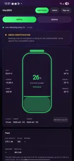
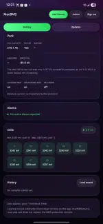
It shows you voltage, current, power, state of charge, temperatures and every cell,
records history, and tells you when the BMS is alarming. It cannot change a
protection limit, cannot start or stop balancing, cannot calibrate anything, cannot
open or close the MOSFETs. The only message it ever sends to the BMS is the read
request. That is deliberate, and here is why.
Why I did not add settings control
• The BMS is your safety layer. Cell over/under-voltage, over-current, over-temp and
short-circuit cut-offs live in it. One wrong write — a wrong cell count, a disabled
protection, a bad calibration value — leaves a lithium pack charging with its
limits removed. That is a fire risk, not a bug you can ρá†ch later.
• Writes cannot be verified the way reads can. Write frames differ between hardware
revisions, are often not acknowledged, and are not documented per firmware version.
A corrupted write stays in the BMS's stored configuration; a corrupted read is just
one bad sample you can ignore.
• It would be remote. The app talks to the gateway over the internet, and the gateway
runs a setup hotspot when it has no Wi-Fi so it stays recoverable when it is mounted
at the battery. Put settings behind that path and anyone who gets in can change how
your pack protects itself.
• Nobody can test it safely. There is no way to rehearse "disable a protection" on a
live pack, and no test that proves it worked. Untested writes to a safety device are
worse than no feature.
So settings, balancing and MOSFET control stay with the BMS front panel or the
vendor's app, in front of the pack. This system tells you what the pack is doing.
It is not a replacement for the BMS protection circuits.
WHICH ESP32 WORKS
 ESP32-WROOM-32 DevKit / NodeMCU-32S / 30- or 38-pin DevKit board, 4 MB flash —
this is exactly what the .exe is built for.
 ESP32-WROVER — only if it has no PSRAM on GPIO16/17 (the image refuses to start
with the UART on those pins, because those are the BMS pins).
✘ ESP32-S3, S2, C3, C6 — different processor and flash layout, needs its own build.
✘ ESP8266 (NodeMCU, Wemos D1) — different chip, not enough RAM.
✘ Any 2 MB ESP32 — refused before writing, it would accept the image and not boot.
The flasher checks the chip and flash size first and refuses politely instead of
half-flashing your board.
WHAT ELSE YOU NEED
- Windows 10/11 PC and a USB DATA cable; if no COM port appears, install the CP210x
or CH340/CH341 driver.
JK BMS 4-pin port ESP32 DevKit
┌─── ─────── ────┐
│ O O O O │
│GND RX TX VBAT│
└─── ─────── ────┘
│ │ │ └── VBAT: NEVER CONNECT
│ │ └─────── BMS TX ──────► GPIO16 (RX)
│ └─────────── BMS RX ◄────── GPIO17 (TX)
└─────────────── BMS GND ─────── GND (connect this first)
Hard rules:
1. NEVER connect VBAT or any battery/power pin to a GPIO — it kills the ESP32.
2. GND must be shared between BMS and ESP32.
3. Data lines cross: BMS TX to ESP RX, BMS RX to ESP TX.
4. The port must be 3.3 V logic-level UART. If it is 5 V, use a level shifter.
5. If your port is a true differential RS-485 pair (A/B), do not wire it to the ESP32
at all — that needs an RS-485 transceiver, which this build does not drive.
6. Power the ESP32 from its own 5 V supply, never from the BMS connector.
7. Pin order varies between revisions. Check with a multimeter before connecting.
STEP BY STEP
1. Plug the ESP32 into the PC with the data cable. Double-click
macBMSmon-flasher.exe. If Windows says "protected your PC": More info → Run
anyway. It finds the port, confirms a 4 MB ESP32, flashes and verifies.
If it cannot connect: hold BOOT, tap EN/RST, release BOOT, run it again.
2. Power off the pack, then wire it as above. Ground first. Double-check VBAT is not
connected to anything.
3. Set the BMS port protocol to "JK BMS RS485 Modbus V1.0" if your model has that
setting — the shipped image speaks JK Modbus at 115200 8N1. (If your port only
ever answers in the default JK mode, this image stays silent.)
4. Power the ESP32 and the pack. After ~15 seconds the ESP32 opens its own hotspot
named MacBMSmon-XXXXXX.
5. First, in the app: create an account, then on the Gateways screen tap "Create
one-time pairing code" and copy the 64-character code (valid 15 minutes, single use).
6. Join the MacBMSmon-XXXXXX hotspot from the phone. The setup page opens by itself;
if not, open You do not have permission to view the full content of this post. Log in or register now.
7. Pick your home Wi-Fi, type the password, paste the pairing code, name the gateway,
tap "Save and connect". The hotspot disappears — that is success; it is now on your
Wi-Fi and registered to your account.
8. Reconnect the phone to your Wi-Fi. The gateway appears on Gateways. Tap it and the
Battery tab goes live, refreshing every 3 seconds. Leave the app and it drops to one
sample a minute, which is what lets it measure real capacity over a full cycle.
IF SOMETHING DOES NOT WORK
- Flasher cannot find the board → charge-only cable, missing CP210x/CH340 driver, or
another program holding the COM port.
answered.
GOOD TO KNOW
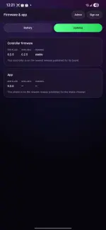
- Updates: the app updates itself (Updates → Update app) and can update the gateway
firmware over the air (Updates → Update firmware). Both are signed and verified on
the device; an update that does not verify is refused.
- Accounts exist so that data is per-owner: your account sees only your gateway; you
can revoke a gateway and pair it to another account.
- Readings are stored on my hosted server so the phone can show history
from anywhere. No analytics, no ads, no sharing.
- Tested on a JK-B2A8S20P. Theoretically, this should work with other models as long as "JK BMS RS485 Modbus V1.0" UART protocol is set on the BMS settings — the driver has several JK
profiles — but I cannot promise your revision answers the same way. Ask before
trusting it for anything important.
- Free, no warranty, use at your own risk. It is a monitoring tool, not a protection
device and not a substitute for watching a pack being charged for the first time.
Always keep the BMS protection settings doing their job.
I built this for my own pack and I'm sharing it with the group. A cheap ESP32 sits
next to the battery, reads the BMS over its UART port, and sends the readings to
your Android phone. You can watch charge/discharge from another room or another
town, not just standing in front of the pack.
WHAT YOU WILL GET
- macBMSmon-flasher.exe (Windows) — double-click it, it finds your ESP32, flashes
it and verifies it. Nothing to install, no Python, no Arduino IDE, no flash offsets.
You do not have permission to view the full content of this post. Log in or register now.
- macBMSmon 0.3.0.apk — the Android app (Android 8.0 or newer).
You do not have permission to view the full content of this post. Log in or register now.
THIS IS MONITORING ONLY. IT CANNOT CHANGE A SINGLE SETTING ON YOUR BMS.It shows you voltage, current, power, state of charge, temperatures and every cell,
records history, and tells you when the BMS is alarming. It cannot change a
protection limit, cannot start or stop balancing, cannot calibrate anything, cannot
open or close the MOSFETs. The only message it ever sends to the BMS is the read
request. That is deliberate, and here is why.
Why I did not add settings control
• The BMS is your safety layer. Cell over/under-voltage, over-current, over-temp and
short-circuit cut-offs live in it. One wrong write — a wrong cell count, a disabled
protection, a bad calibration value — leaves a lithium pack charging with its
limits removed. That is a fire risk, not a bug you can ρá†ch later.
• Writes cannot be verified the way reads can. Write frames differ between hardware
revisions, are often not acknowledged, and are not documented per firmware version.
A corrupted write stays in the BMS's stored configuration; a corrupted read is just
one bad sample you can ignore.
• It would be remote. The app talks to the gateway over the internet, and the gateway
runs a setup hotspot when it has no Wi-Fi so it stays recoverable when it is mounted
at the battery. Put settings behind that path and anyone who gets in can change how
your pack protects itself.
• Nobody can test it safely. There is no way to rehearse "disable a protection" on a
live pack, and no test that proves it worked. Untested writes to a safety device are
worse than no feature.
So settings, balancing and MOSFET control stay with the BMS front panel or the
vendor's app, in front of the pack. This system tells you what the pack is doing.
It is not a replacement for the BMS protection circuits.
WHICH ESP32 WORKS
ESP32-WROOM-32 DevKit / NodeMCU-32S / 30- or 38-pin DevKit board, 4 MB flash —this is exactly what the .exe is built for.
ESP32-WROVER — only if it has no PSRAM on GPIO16/17 (the image refuses to startwith the UART on those pins, because those are the BMS pins).
✘ ESP32-S3, S2, C3, C6 — different processor and flash layout, needs its own build.
✘ ESP8266 (NodeMCU, Wemos D1) — different chip, not enough RAM.
✘ Any 2 MB ESP32 — refused before writing, it would accept the image and not boot.
The flasher checks the chip and flash size first and refuses politely instead of
half-flashing your board.
WHAT ELSE YOU NEED
- Windows 10/11 PC and a USB DATA cable; if no COM port appears, install the CP210x
or CH340/CH341 driver.
- Android 8+ phone.
- 2.4 GHz Wi-Fi (the ESP32 has no 5 GHz radio).
- The BMS 4-pin UART cable and a multimeter.
- A 5 V phone charger for the ESP32 once it is installed.
JK BMS 4-pin port ESP32 DevKit
┌─── ─────── ────┐
│ O O O O │
│GND RX TX VBAT│
└─── ─────── ────┘
│ │ │ └── VBAT: NEVER CONNECT
│ │ └─────── BMS TX ──────► GPIO16 (RX)
│ └─────────── BMS RX ◄────── GPIO17 (TX)
└─────────────── BMS GND ─────── GND (connect this first)
Hard rules:
1. NEVER connect VBAT or any battery/power pin to a GPIO — it kills the ESP32.
2. GND must be shared between BMS and ESP32.
3. Data lines cross: BMS TX to ESP RX, BMS RX to ESP TX.
4. The port must be 3.3 V logic-level UART. If it is 5 V, use a level shifter.
5. If your port is a true differential RS-485 pair (A/B), do not wire it to the ESP32
at all — that needs an RS-485 transceiver, which this build does not drive.
6. Power the ESP32 from its own 5 V supply, never from the BMS connector.
7. Pin order varies between revisions. Check with a multimeter before connecting.
STEP BY STEP
1. Plug the ESP32 into the PC with the data cable. Double-click
macBMSmon-flasher.exe. If Windows says "protected your PC": More info → Run
anyway. It finds the port, confirms a 4 MB ESP32, flashes and verifies.
If it cannot connect: hold BOOT, tap EN/RST, release BOOT, run it again.
2. Power off the pack, then wire it as above. Ground first. Double-check VBAT is not
connected to anything.
3. Set the BMS port protocol to "JK BMS RS485 Modbus V1.0" if your model has that
setting — the shipped image speaks JK Modbus at 115200 8N1. (If your port only
ever answers in the default JK mode, this image stays silent.)
4. Power the ESP32 and the pack. After ~15 seconds the ESP32 opens its own hotspot
named MacBMSmon-XXXXXX.
5. First, in the app: create an account, then on the Gateways screen tap "Create
one-time pairing code" and copy the 64-character code (valid 15 minutes, single use).
6. Join the MacBMSmon-XXXXXX hotspot from the phone. The setup page opens by itself;
if not, open You do not have permission to view the full content of this post. Log in or register now.
7. Pick your home Wi-Fi, type the password, paste the pairing code, name the gateway,
tap "Save and connect". The hotspot disappears — that is success; it is now on your
Wi-Fi and registered to your account.
8. Reconnect the phone to your Wi-Fi. The gateway appears on Gateways. Tap it and the
Battery tab goes live, refreshing every 3 seconds. Leave the app and it drops to one
sample a minute, which is what lets it measure real capacity over a full cycle.
IF SOMETHING DOES NOT WORK
- Flasher cannot find the board → charge-only cable, missing CP210x/CH340 driver, or
another program holding the COM port.
- No hotspot → no power, or it already has a saved network; power-cycle it.
- Pairing done but readings empty → BMS not wired, or the port is in the other
answered.
- Values look wrong → wrong model or protocol profile selected when the code was made.
- Reading up to a minute old → nobody is watching; opening the dashboard brings back
GOOD TO KNOW
- Updates: the app updates itself (Updates → Update app) and can update the gateway
firmware over the air (Updates → Update firmware). Both are signed and verified on
the device; an update that does not verify is refused.
- Accounts exist so that data is per-owner: your account sees only your gateway; you
can revoke a gateway and pair it to another account.
- Readings are stored on my hosted server so the phone can show history
from anywhere. No analytics, no ads, no sharing.
- Tested on a JK-B2A8S20P. Theoretically, this should work with other models as long as "JK BMS RS485 Modbus V1.0" UART protocol is set on the BMS settings — the driver has several JK
profiles — but I cannot promise your revision answers the same way. Ask before
trusting it for anything important.
- Free, no warranty, use at your own risk. It is a monitoring tool, not a protection
device and not a substitute for watching a pack being charged for the first time.
Always keep the BMS protection settings doing their job.